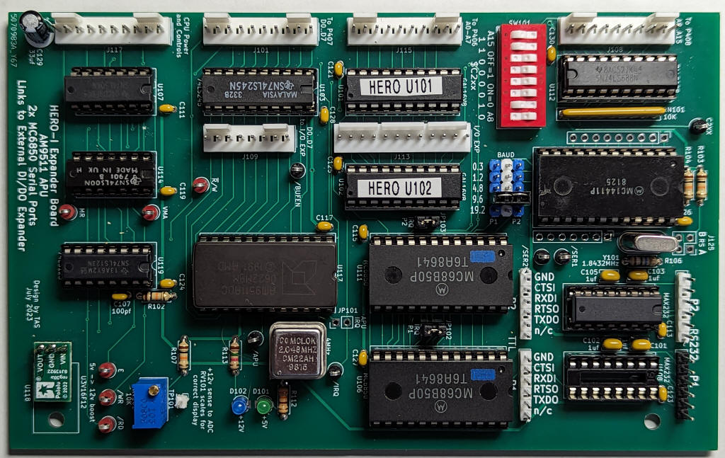
This project is a set of boards to extend the I/O capabilities of the HERO-I robot. One board mounts internal to HERO's chassis, sandwiched with the Heath memory expansion card. This internal board provides an AM9511 APU, two interrupt-capable serial ports, and decoding and buffering for an external card. The external card mounts on the rear of the battery tray, and provides two digital input ports, two digital output ports, and a multiplexed 8-channel ADC. HERO's leisurely 1MHz CPU speed makes it possible to implement this expansion with standard ribbon cable interconnects.
The Motorola 6800 family 6850 was used for the serial ports. A software program was written to treat one of the serial ports as an interrupt-driven console, which makes terminal I/O simpler than using the bit-bang serial port that is standard on HERO. TTL and RS-232-level signals are available for both serial ports. The AMD AM9511 APU is used to simplify "motor math" - calculating position vectors of HERO's various motors. The AM9511 was also used in the similar vintage Heathkit H8 computer.
The internal card connects to HERO's CPU using the three bus connectors that Heath provided on the CPU board: P408 (A8-A15), P406 (A0-A7), and P407 (D0-D7). Address decoding requires the VMA, clock (E) and R/!W signals; the APU needs access to the MR (Memory Ready) signal. Those signals were picked up directly from the HERO memory expansion card. Interrupts use the Experimenter Board IRQ line. Two GALs are used to do address decoding for the eight expansion devices on these two cards.
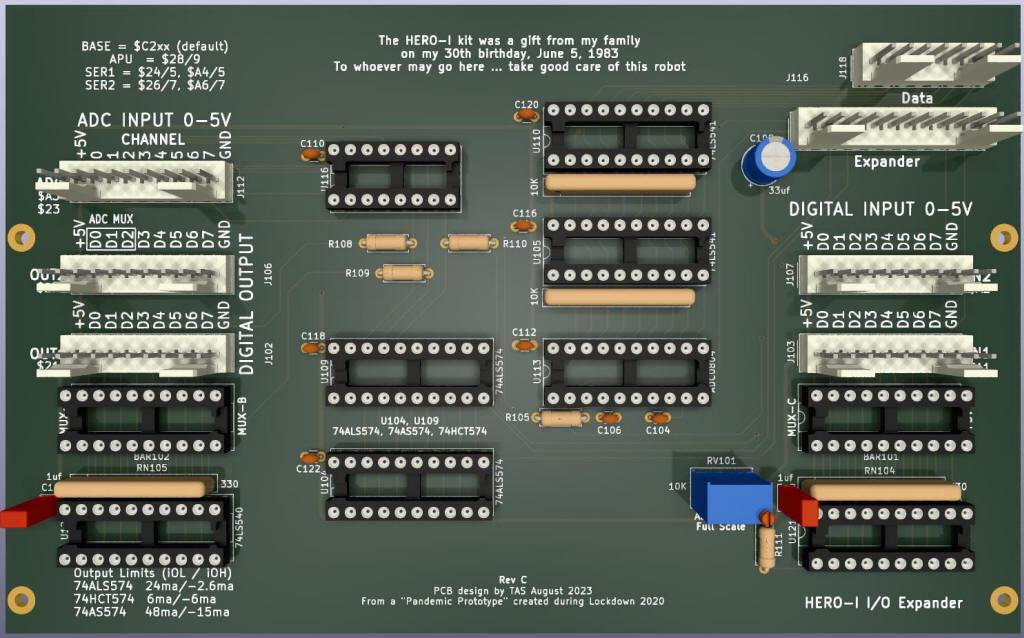
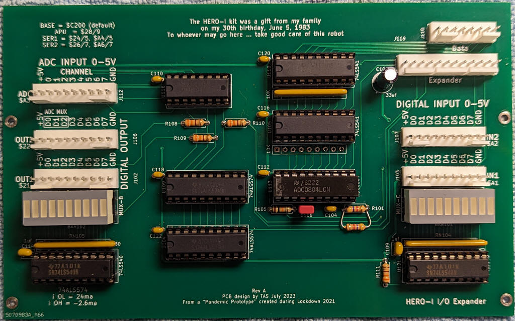
The external card holds the two (each) 8-bit input and output ports, an 8-channel analog multiplexer, and an 8-bit ADC. The DI and DO ports use the 5xx series equivalents of the 74LS244 and and 74LS374 that are used on HERO's I/O card. The 8-bit ADC is the ADC0804 chip, which is also used in HERO's Sense board (for light and sound sensing). To add some "Blinkenlights" fun on this otherwise sparse board, 10-segment LED bar graphs were added to show the status of one input and one output port. I have used one of the expansion digital inputs for a Sparkfun line-follower bar, one digital output drives a 4-line LCD display that augments HERO's built-in 7-segment display. The ADC is used to interface joysticks on a revised remote control. The joystick control is much easier to use than the switches on the standard remote - HERO is easily "driveable" with the joysticks.
The Internal card can be used standalone, without connecting the external card. The external card must be used with the internal card. Getting access to a few of the CPU control signals does mean that once HERO is wired for the internal card, a jumper plug must be installed if the internal card is removed. Excepting the need for that jumper plug, none of HERO's factory functions are altered by these cards.
For the ~150ma of +12v power required by the AM9511, I elected to use a Pololu 5v->12v boost converter. The +12v logic supply has always felt "dirty" to me - prone to voltage variation as batteries discharge or high-current motors are switched on and off (on the alternate +12v supply). My bet was that the on-board boosted +12v would be cleaner.
The original handwired prototype for this board was produced during the 2021 pandemic lockdown. A PCB was produced in July of 2023 to formalize the project installation.
| Schematic: Internal Card (Serial and APU) | Internal Card X-Ray View | Bill of Materials | Jumper Settings |
| Schematic: External Card (DI/DO/AI) | External Card X-Ray View | Bill of Materials | Jumper Settings |


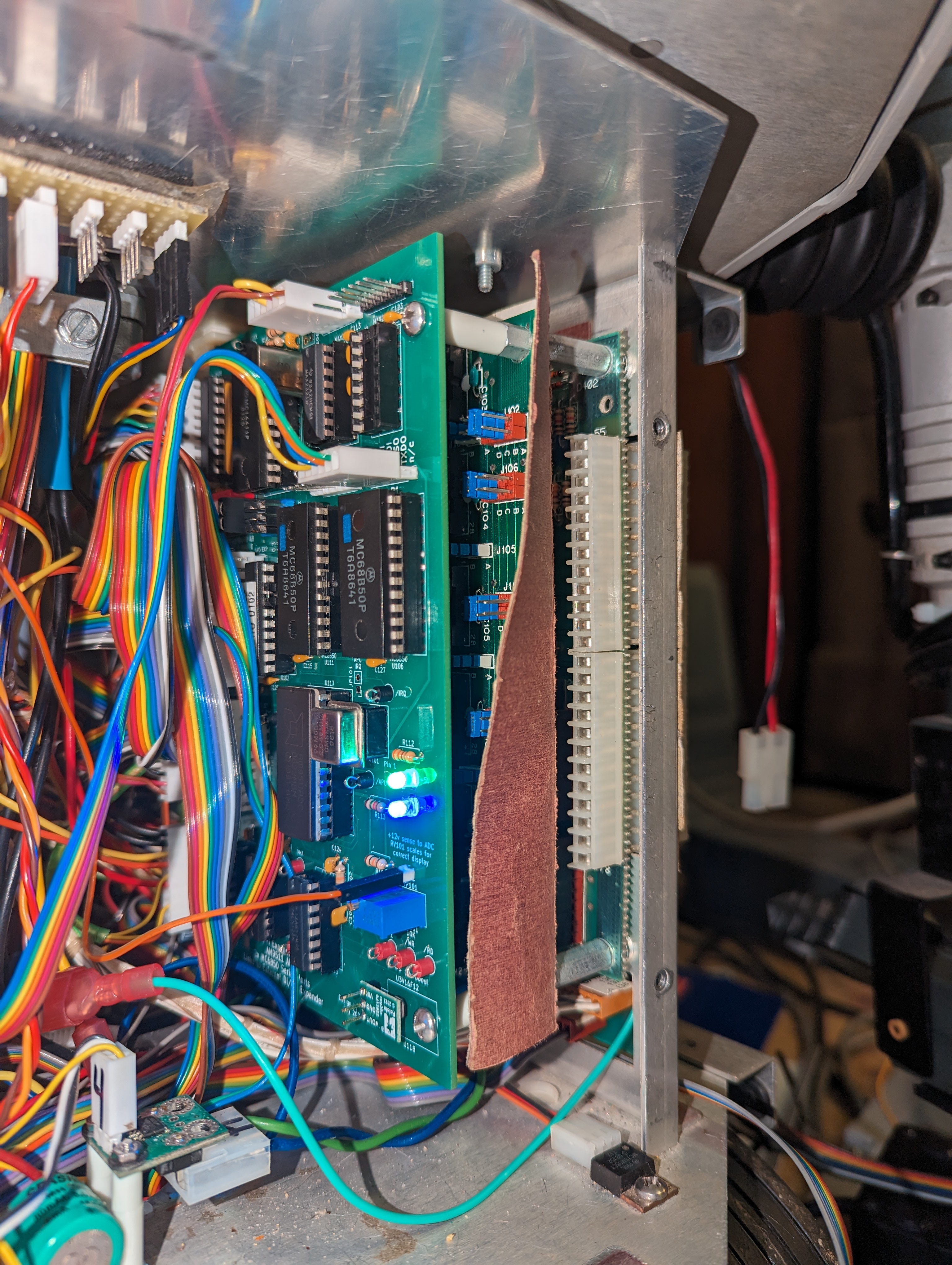
Internal (above) and External (below) expansion cards. Internal card is
mounted piggy-back with the HERO memory expansion card
The external card is mounted to the back of the (lower) battery tray.


