H8 Backplane
This project takes Norberto Collado's latest H8 backplane and adapts it for my use cases. Disclaimer: There is nothing wrong with Norberto's design. It is just optimized for a use case that is different than mine.
![]() I ended up with two versions of the backplane: A minimalist one that
satisfies my requirements, and a full-featured version that has most of the
features of Norberto's earlier design, including the PC supply control circuit
(555 timer).
I ended up with two versions of the backplane: A minimalist one that
satisfies my requirements, and a full-featured version that has most of the
features of Norberto's earlier design, including the PC supply control circuit
(555 timer).
I wanted a backplane that would:
|
Have solderless connector options for use with any PC chassis - Heath OEM or a replacement | |
|
Support linear as well as switched supplies (but not a supply designed for a PC) | |
|
Fit without restriction into the Heath OEM case, including the supply/capacitor shield | |
|
Optimize bus signal quality by eliminating signal pathways I don't use (the half-card slots and the split bus for two CPUs) | |
|
Keep it as simple as possible - eliminate the PC supply startup circuitry, stick with the Heath linear supplies or switched equivalents | |
|
Have fast-acting protection of the high-current +8v supply |
I wanted to experiment with a 4-layer design to see if that would improve signal reflections. The Trionyx backplane used a three-layer design, with a middle ground plane. Can't (easily) get three layers today, but a common 4-layer stackup is signal-ground-ground-signal which fits the backplane nicely. With the luxury of four layers, I elected to try an alternating front-to-back arrangement of the 50 bus lines. That should be effective at reducing crosstalk between adjacent bus lines, but I have no evidence that crosstalk has been an issue with any of the H8 backplanes.
I opted to use an integrated bridge rectifier rather than the four discrete 1N4007s in the original supply design. It just seemed a little tidier, although I can make no compelling case for choosing one design over the other. Power to the backplane can come via via the ATX connector, or two Molex KK396 connectors (3-pins for the AC transformer input to the +/-18v on-board supply, and 4-pins for the +8v supply). KK396 connector pins were doubled on the +8v supply to allow parallel 18ga connections. The solder pads for the +8v supply have big enough holes for up to 14ga wire if you insist on soldering direct to the board. The +/-18v filter capacitors were changed to radial lead so that the entire linear supply, and all of the power input connectors, fit underneath the metal power supply shield on the OEM chassis. The +8v supply is protected with a fast-acting 1/4" (3AG) fuse located at the top of the backplane where it is accessible in the OEM or a custom case.
Auxiliary power outputs from the backplane are provided in two connectors: A four-pin KK254 connector can connect directly to a chassis fan. An adjacent jumper selects which voltage you want to apply to the fan. A four-pin KK396 connector provides auxiliary access to both the +8v and +18v supplies (or +5/+12v if you are using those voltages from switching supplies).
The silkscreen outline around the +/-18v linear supply marks where the OEM metal supply shield fits against this board. The "keepout" zone at the top of that space guarantees no interference with the speaker that mounts to the top of the supply shield.
On the version of this board with the 555 timer, there are multiple options for controlling a PC-ATX power supply:
|
Switch the AC power to the ATX supply on/off. There are no special connections to the board required to do this. This method is also used with the "timerless" board. | |
|
Leave the AC power to the ATX supply "on" at all times. Use a (low voltage, low current) toggle switch connected to header J103 to turn the ATX supply on and off. | |
|
Leave the AC power to the ATX supply "on" at all times. Connect a (low voltage, low current) momentary contact pushbutton to header JP{101 for "push on / push off" operation. |
| Schematic | Bill of Materials | Board X-Ray View | KiCAD Development Files (editable) |
| Schematic (full version) | Board X-Ray View (full) | ||
| Options for Powering the H8 |
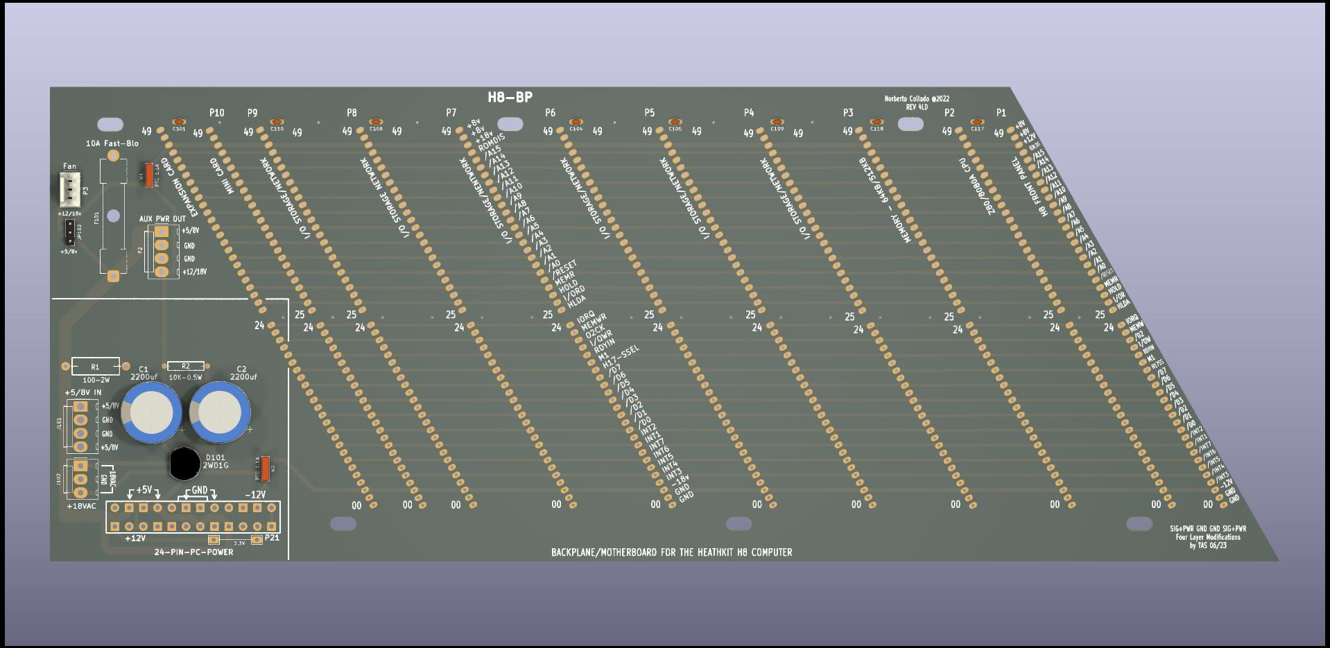
ABOVE: "Minimalist" version. Can be powered either with Heath OEM-style linear transformer/supply, or with switched DC supplies (including PC-ATX).
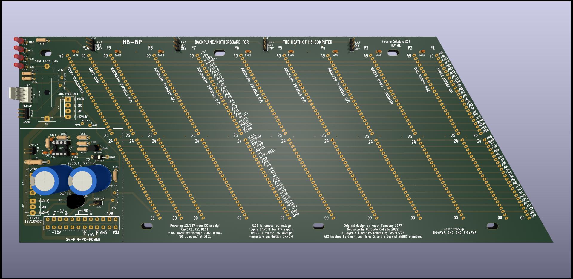
BELOW: Full-featured board with timer on/off circuit for PC-ATX supply, LEDs for all supplies, and 3.3v/Standby power headers. The circuit design is the same as what Norberto used. The board offers some mechanical rearrangements from his board.
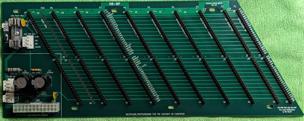
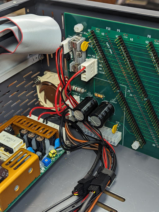
Above: Assembled "minimalist" backplane, with +/-18v supply components installed
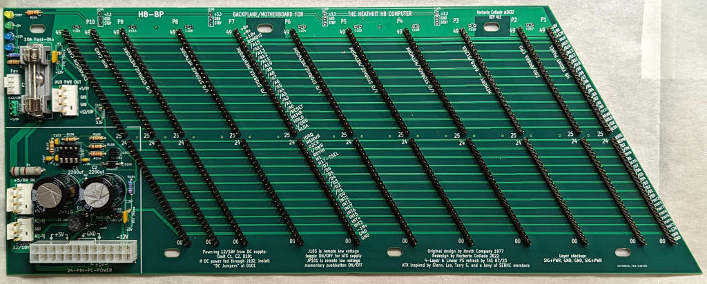
Below: Assembled "full feature" backplane
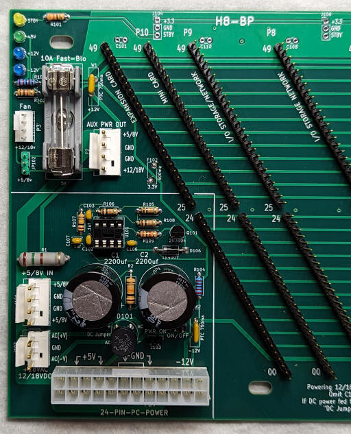

Detail of +/-18v linear supply and the 555 PC-ATX on/off circuit. Bridge rectifier 2W01G is mounted with 3/8" clearance to board surface as recommended in datasheet. ATX connector and Molex KK396 connectors are wired in parallel so either may be used.
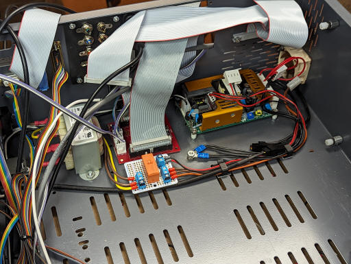
Detail of installation into Protocase chassis. This installation uses a switching 9v supply and a transformer to feed the on-board linear +/-18v supply. Molex KK396 connectors are used for power to the backplane and auxiliary power out. A Molex KK254 (0.1") 4-pin header uses standard 3- or 4-pin fan wiring scheme, jumper selectable between +5/8v and +12/18v. A fast-blow 1/4" 3AG fuse protects the +5/8v supply. On my fully populated system, I measure +8v current draw of about 3A. It is fused at 10A. The fuse is easily replaced from the top of the cabinet.