H8 I2C <-> SPI Bridge
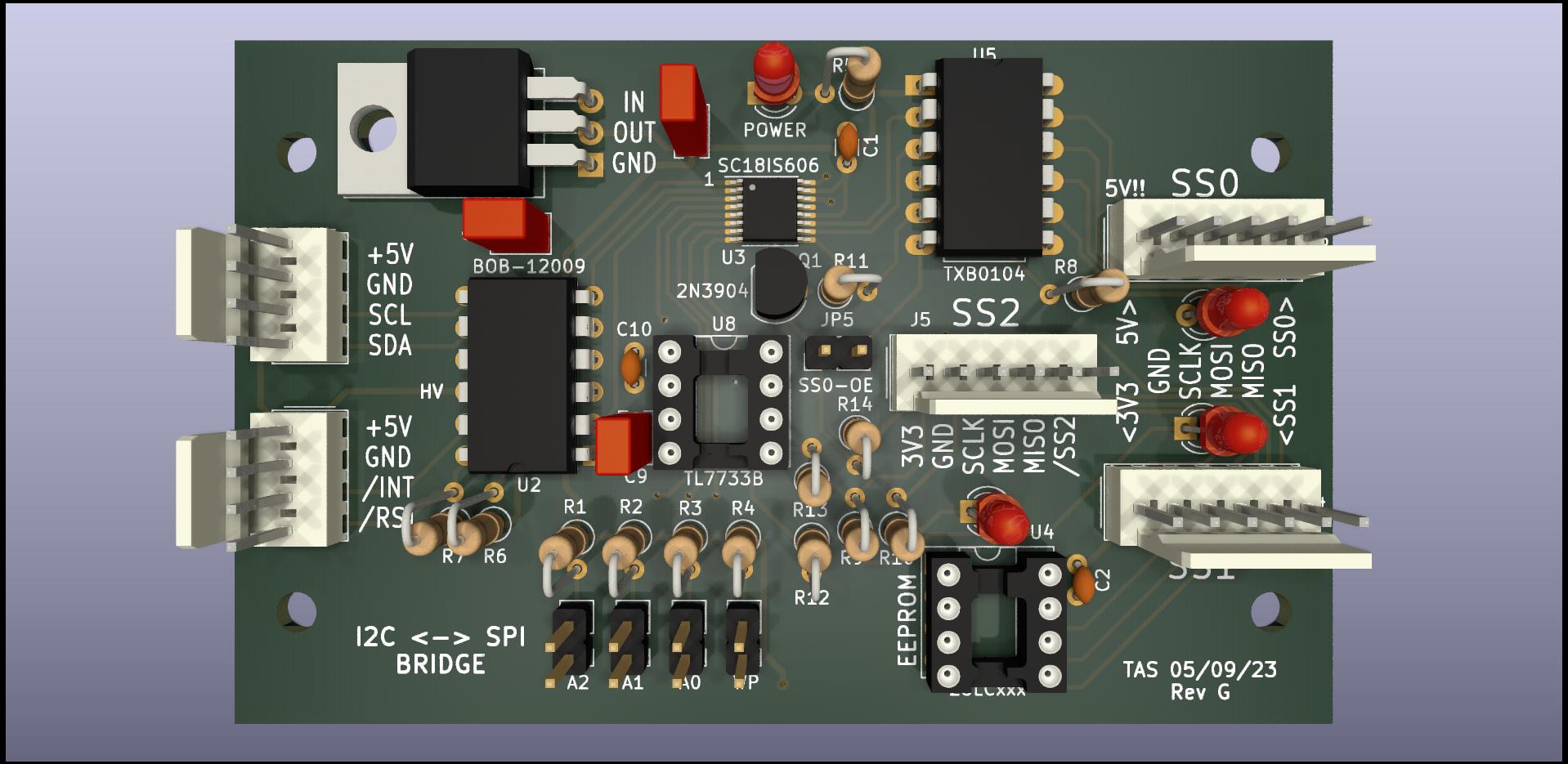
This small external board (about 2" x 3") leverages the I2C controller included on the System Support II and 8255 PPIO board to provide up to three SPI channels. The board is based on the NXP (Philips) SC18IS606 chip. The board is socketed for an optional 25LCxxx serial EEPROM. The EEPROM uses one of the three available select signals, so if the EEPROM is populated, there are two SPI channels open for other uses. A Sparkfun BOB-12009 4-channel level shifter adapts the H8's 5v I2C bus to the 3v bus required by the bridge chip. The BOB-12009 was found to be too slow to the provide level translation of the SPI signals, so the TI TXU0304 chip is used. This active translator is specifically designed for SPI translation, providing three forward circuits for CLK, MOSI, and CS plus one reverse for MISO. Of the three SPI channels from the SC18IS606, one is level-shifted to 5v while the other two operate at 3.3v. Since this board might be plugged or unplugged into the I2C connection at any time, a TL7733B reset controller was included to properly reset the SC18IS606 even with a "dirty" powerup. Surface mount components are used wherever possible. The board was sized to fit within a Hammond 1591XX-BBK ABS box.
The MIKROE-3743 "I2C to SPI Click" board plus the NXP SC18IS606-EVB and TI TXU-EVM evaluation boards were used to prototype this circuit.
This bridge is best suited to low- to medium-speed transfers, such as those found on sensors or motor control boards. The speed of the circuit is limited by the 400kbps bandwidth of the I2C connection. A "bare metal" SPI solution would permit operation (of some SPI devices) to speeds well into the mbps. Douglas Miller, for example, has a discrete hardware SPI solution on his H8xSPI board that can drive the WizNET networking module at 16mbps. However, there are reasons to use a slower-speed SPI bus that is not tied to the CPU clock speed. For example, you may be interested in connecting to a somewhat distant device where maintaining the integrity of very high speed (CPU-clocked) SPI signals would be difficult or impossible. For many sensor devices with modest data rates, a reliable, modest speed SPI or I2C connection can be made over distances of several meters using simple ribbon cable.
Supply chain note: The TXU0304PW (TSSOP-14 package) has been difficult to source. As of 7/31/23, it appears to be getting restocked at the first tier suppliers. Mouser has some inventory, and Digikey is showing August 2023 for lead time. The TXU chip is not available in a thru-hole package.
| Schematic | Board X-Ray View | Bill of Materials | Jumper Settings |
| Board X-Ray View (Thru Hole) | |||
| SC18IS606 Datasheet | 25LC EEPROM Datasheet | ||
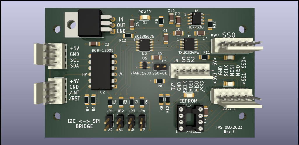
Surface Mount Version Above
Thru Hole Version Below
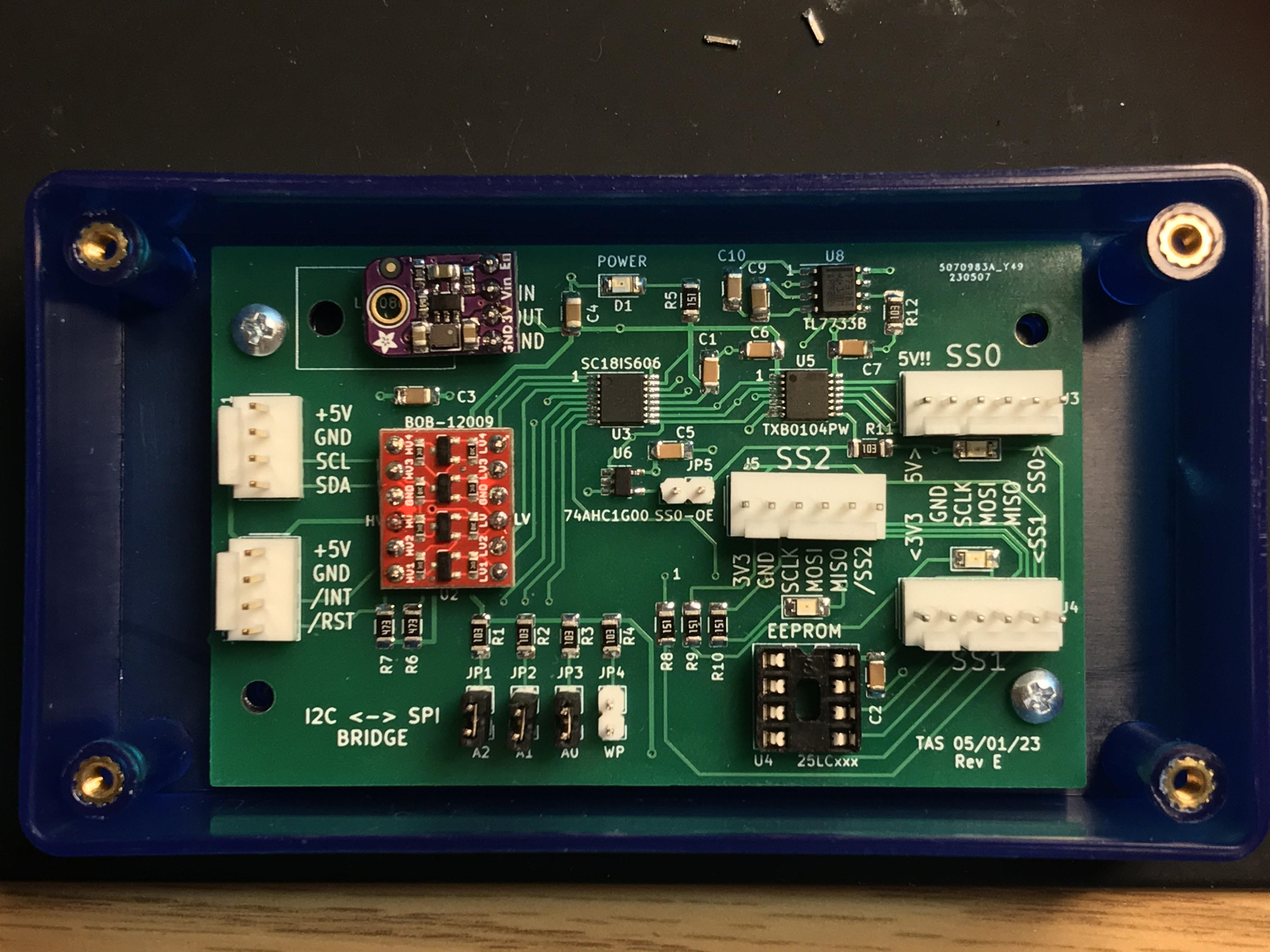
(Rev E board photographed mounted inside a Hammond 1591XX-BBK)
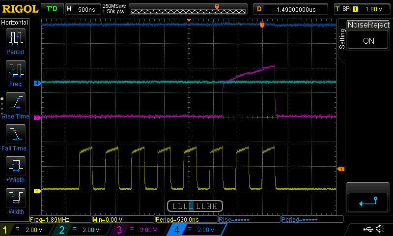 |
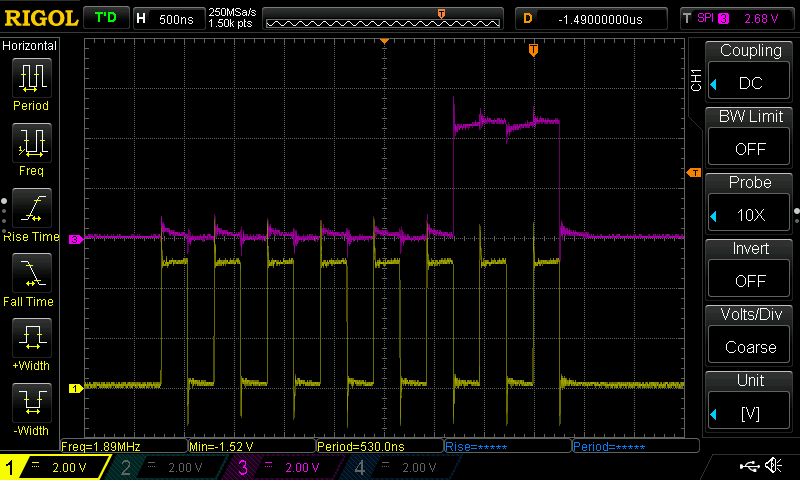
Yellow: SCLK Magenta: MOSI Trace of "03H" being transmitted ~2MHz SPI clock Output pulses begin at ~3v and slowly climb |
 |
Yellow: SCLK Magenta: MOSI Trace of "03H" being transmitted ~500KHz SPI clock Output pulses begin at ~3v and slowly climb. Almost get to 5v at this slower clock speed.
|
 |
Yellow: SCLK Magenta: MOSI Trace of "03H" being transmitted ~2MHz SPI clock The TXB0104 uses active edge acceleration. The leading and trailing edges on these pulses are extremely fast , causing some overshoot and ringing (at least some of which is resulting from my scope and probes). The pulses quickly reach ~5v and remain stable for the duration of the pulse. |
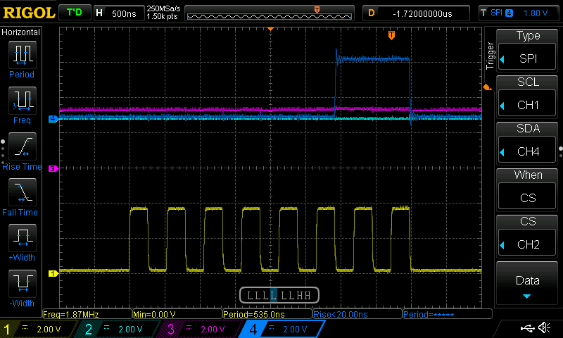 |
Yellow: SCLK Blue: MOSI Trace of "03H" being transmitted ~2MHz SPI clock Very clean waveforms, with very little overshoot or ringing. Pulses rise to ~3.5v quickly and remain stable.
|