"Cherry MX" Keyboard for Heathkit H19/H89 Terminal
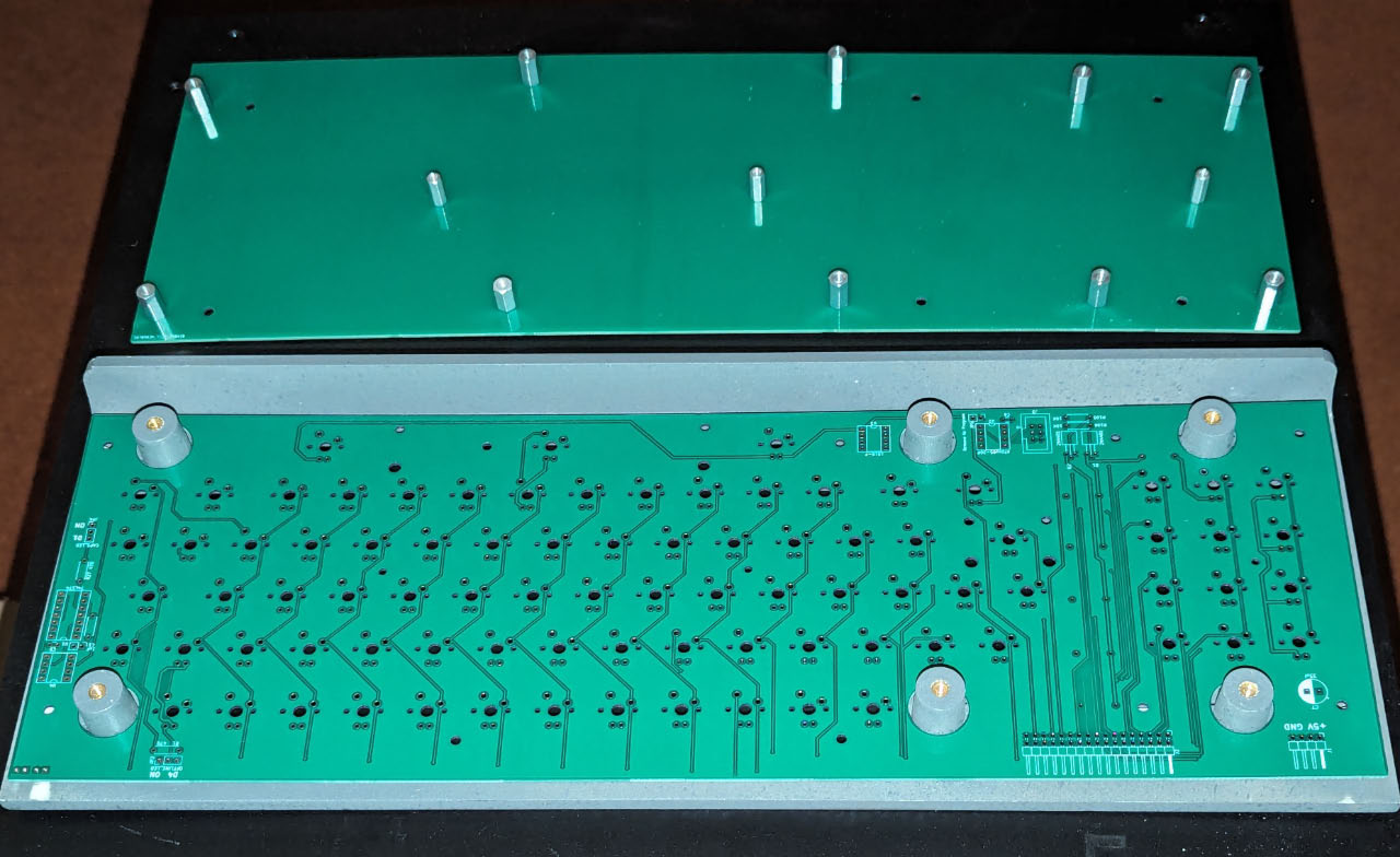
A two-piece keyboard PCB assembly has been designed to fit into the Heathkit H19/H89 terminal chassis and enclosure. The new PCBs use Cherry-MX keyswitches, or one of the many switches that are compatible with the Cherry-MX form factor. The PCB optionally supports adjustable backlighting and/or an auto-repeat circuit that eliminates the need to use a separate "REPEAT" key as found on the OEM H19 keyboard. Multiple versions of the PCB have been created to allow connection to the H19 Terminal Logic Board via the OEM 34-pin ribbon cable, or to a PC or terminal emulator using a USB connection.
An ATTiny85 is used to handle the (optional) PWM backlighting and the auto-repeat function. For the USB versions, a Sprintek SK5210 controller chip is used to handle debouncing, key mapping, auto-repeat, PWM lighting control and the USB interface.
Custom backlit or printed keycaps were produced by MAXKEYBOARD.COM, from an .SVG graphics file developed in Inkscape.
PCBs connected to the H19 TLB require access to unregulated +8v power direct from the H19/89 power supply. An onboard +5v regulator maintains clean +5v power dedicated to the keyboard PCB. The power demand of the backlight LEDs is large enough (and "peaky" enough) that attempting to power the keyboard PCB directly from +5v on the H19 Terminal Logic Board will result in unacceptable video interference.
| PCB Schematic (TLB-attached) | ATTiny85 firmware sketch (for Arduino IDE) | Keycap graphics (backlit) [editable] | Keycap graphics (printed) [editable] |
| PCB Schematic (USB-attached) | Keycap graphics (backlit) objects as path, ready to submit, non-editable |
Keycap graphics (printed) objects as path, ready to submit, non-editable |
|
| Sprintek SK5210 USB interface Schematic | |||
Front design view of a TLB-attached keyboard PCB (KiCAD v7):
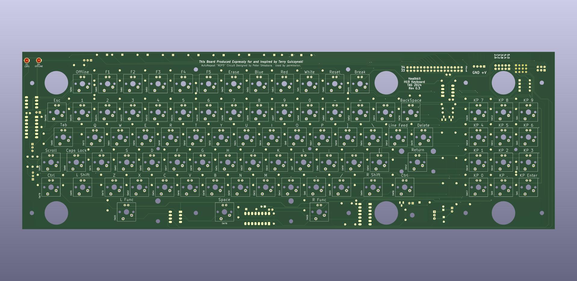
Rear design view of a TLB-attached keyboard PCB. All components excepting the keyswitches themselves are mounted on the back side of the PCB (KiCAD v7):

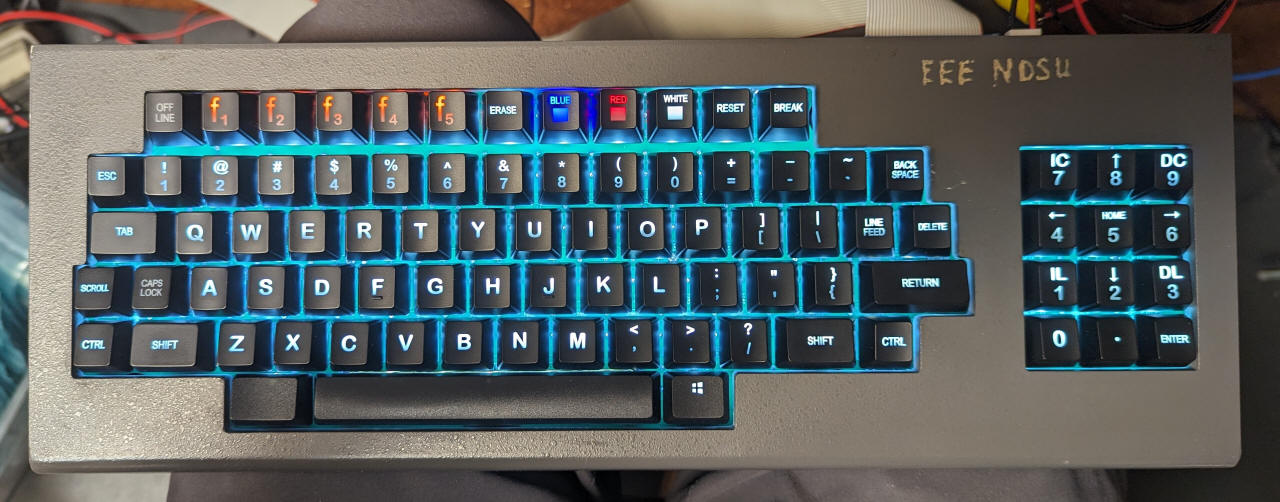
Photograph of a backlit PCB installed into an H19 bezel:
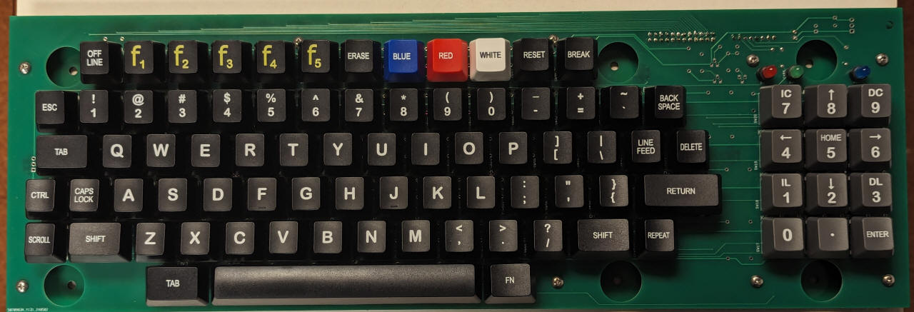
Photograph of a non-backlit (printed) version of the PCB ready for installation into an H19:
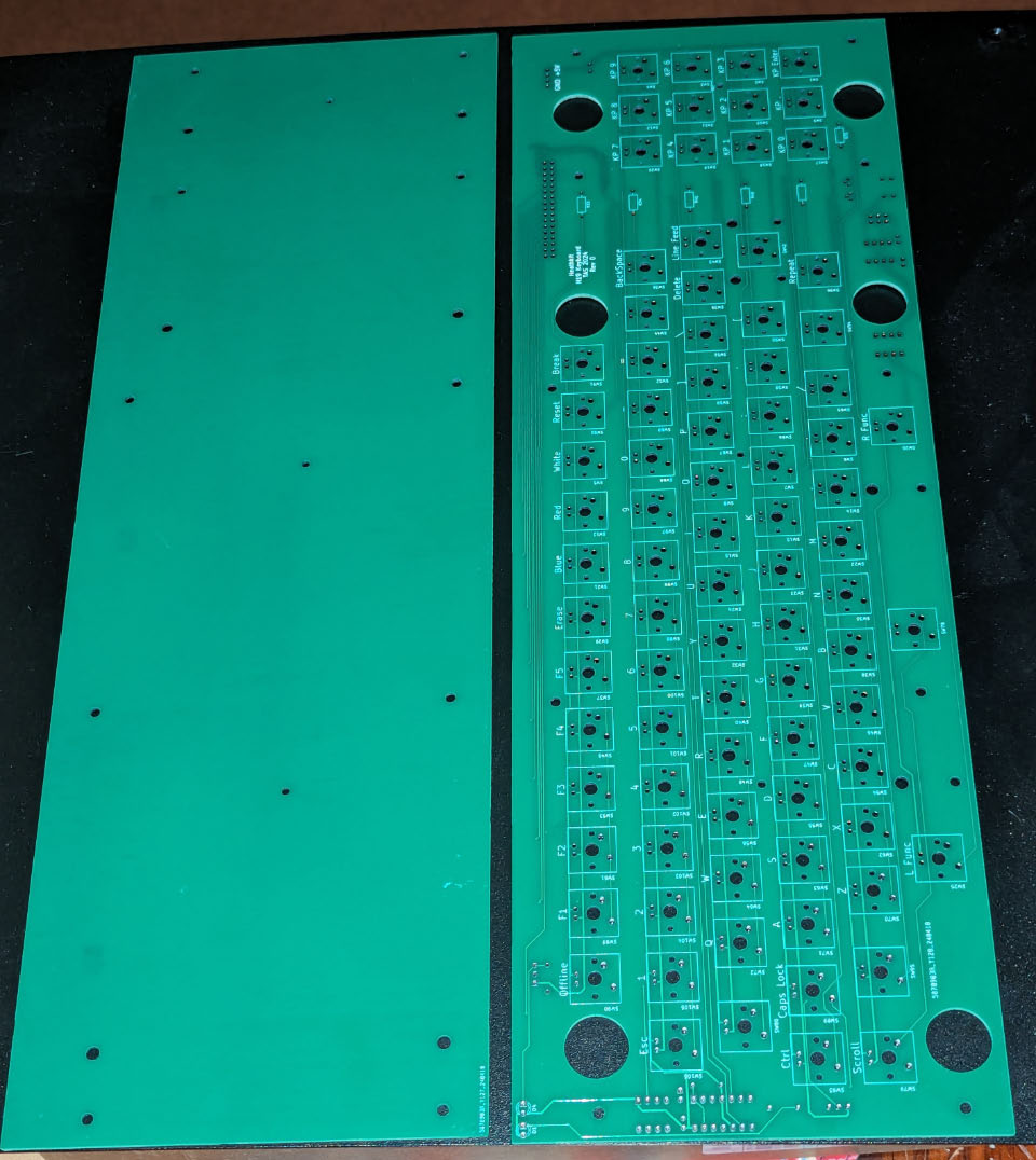
Two PCB set - left is a backpanel that attaches to the H19 mounting bosses, right is the keyboard PCB that slips over the mounting bosses to locate the Cherry-MX switches in the proper position for access through the H19 chassis bezel:
Keyboard PCB fits over the mounting bosses:
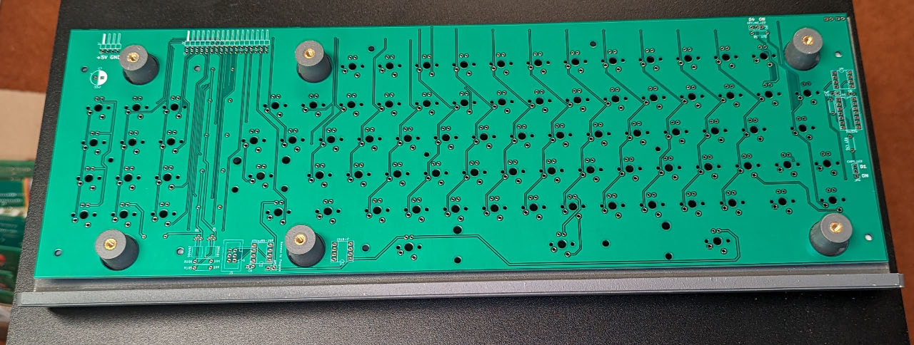
7/16" hex threaded spacers attach the two PCBs together into a rigid "sandwich" that attaches to the back of the mounting bosses:
